Manta Test Systems

Test Equipment for Relay Testers by Relay Testers

  • Home
  • Products
    • MTS-5100 Protective Relay Testing System
    • MTS-2000 Panel Meter and Transducer Test System
    • MTS-1010/1030 Substation Power Meter
  • Services
    • Manta Services
    • Training for Relay Testers
  • Our Blog
  • Customer Area
    • User Forum
    • Online Training
    • Technical Support
    • Training for Relay Testers
  • About Us
  • Contact Us
  • Useful Links

Symmetrical Components Made Easy – Part 2

April 8, 2014 By Kevin Donaldson

In the last post (Symmetrical Components Made Easy – Part 1), we examined and calculated the symmetrical components in a non-faulted three-phase electrical power system. This post expands on the same analysis of using phasor to describe, understand, visualize and calculate the three symmetrical components: Positive, Negative and Zero Sequence components. An examination of a phase to neutral (also referred to as phase to ground) fault will be conducted.

Positive Sequence Components B-N Fault

positive sequence ph_n fault

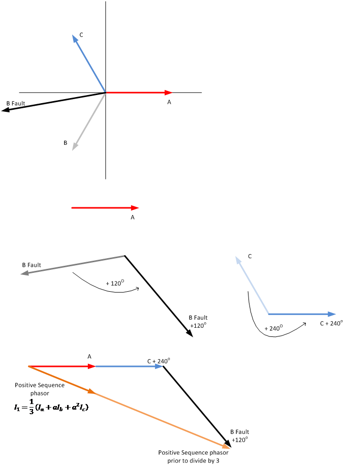
Thus, there is significant positive sequence in the phase to neutral fault and the positive sequence phasor is lagging the reference phase (phase A).

 Negative Sequence Components B-N Fault

negative sequence ph_n fault

Thus, there is some negative sequence in the phase to neutral fault and the negative sequence phasor is leading the reference phase (phase A).

Zero Sequence Components B-N Fault

zero sequence ph_n fault

Thus, there is some zero sequence in the phase to neutral fault.

Conclusion:

  • Sequence components can be calculated and illustrated through the use of phasor diagrams for a phase to neutral fault.
  • There is positive, negative and zero sequence components in a B-N fault; whereas a non-faulted system has only positive sequence – see “Symmetrical Components Made Easy – Part 1”

Filed Under: Electrical theory

Contact Us for More Information

Your Name (required)

Your Email (required)

Subject

Your Message

Please type the text below to prove you are not a robot
captcha

Follow us at:

  • Facebook
  • LinkedIn